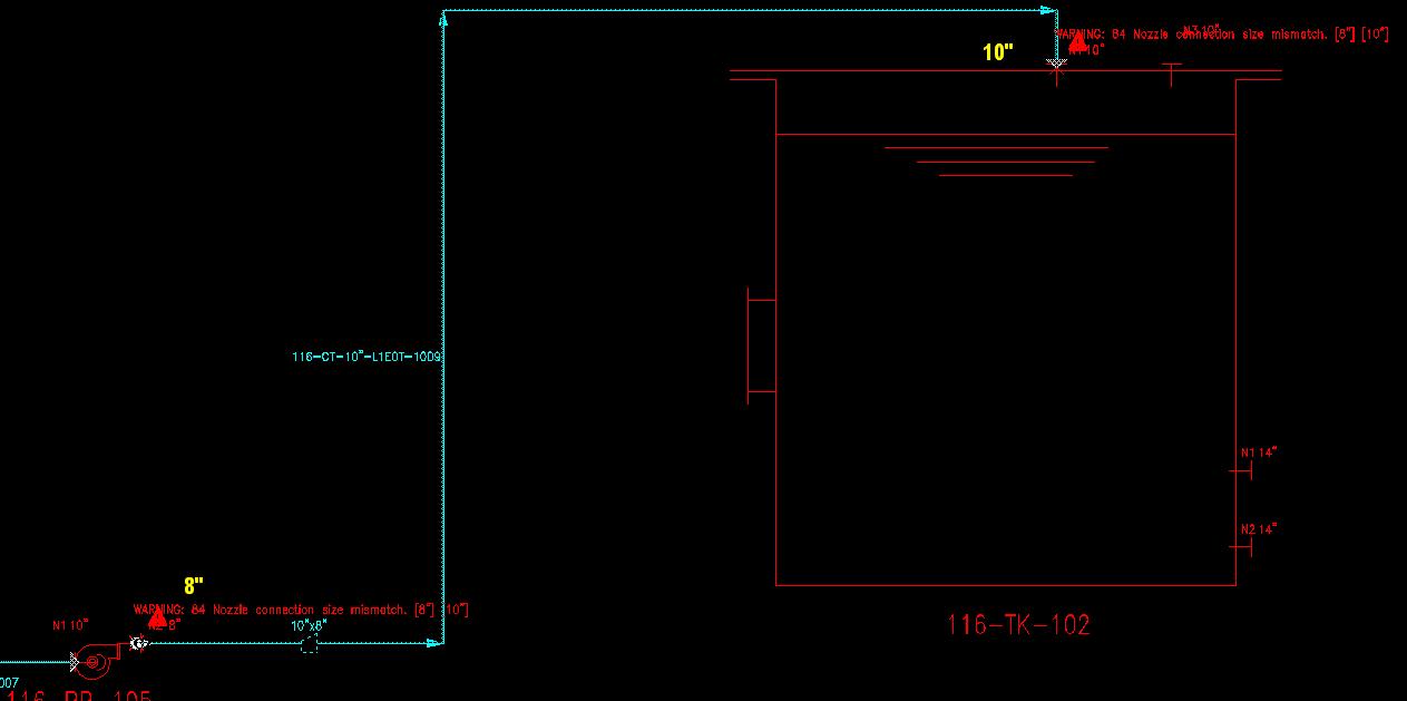
You've got your line labeled incorrectly. Remember that the INLET side of the reducer always appears on the LEFT of the labe. In your thumbnail, it's got 10 first and then 8. It means you need to erase the reducer, set the line start size to 8, then reinsert the reducer and set the downstream size to 10.
Yes, they are. And they are annoying. Unlike the AutoCAD tool, there is no way to anchor a connection across drawings. So if the line data changes at all on one but not the other, the connection is lost. Very frustrating. And I'm having to strangle people to get their marks to have continuity across the P&IDs so my drafters can follow through.
I've built an XLS spreadsheet that pulls all the unresolved lines so we can quickly scan for mismatches. Every time I hand a printout to the process group to fix marks, they grumble, but they are learning.
What I find ironic is that most people in the industry hear the term "intelligent drawing" and think it is a spontaneous occurence. They don't realise that someone has to sit down and think and then put those thoughts into the drawing. In fact, it usually takes MORE design experience on the drafting side to be able to create higher end documents. The only real difference between "intelligent" and regular is that the intelligent ones can be machine read.
How difficult is that concept? Why can't people get it?
You'd better be careful! You're going to get me on my soap box and I have a hard time stopping once I get started.
:angry:
I had a guy I was training once ask me, "If it can draw the pipes, why can't it draw the whole plant for us?" I think it took me a week to recover from that one.
So the guy/gal who draw the P&ID is not someone they can drag from street and has to be someone know something about plant design/process engineering and maybe instrument naming convention...
I think next time you should offer the guy some popcorn (with optional butter) and ask him if he would like to use the THX or Dolby, or how large a plasma TV he would like to watch it from...:teeth_smile:
The difference you see is based on what you have drawn and what the system sees as the main pipe size. By default, VPE P&ID sees the starting size of the line as the default size, and this is what it will show in the Engineering Explorer. If you want a different size to be the main size, then you need to set it manually.
The problem I see is that your 6" size label is actually sitting on an 8" section of pipe, so your graphical representation is incorrect. If you want the pipe labelled as 6", then you need to move the right hand reducer over.
If you want the pipe labelled correctly, then you need to delete the label that you have shown and place a new one off the upstream reducer (the 4x8).
And finally, if you want to set the main pipe size to be other than the starting point, you need to select the label that has the correct size you want, right click, and then choose "Set As Main". At my company, the largest diameter pipe is the main pipe size we want to see in the navigator (and eventually in the line list). So our drafters have to set the main size manually in some cases. They really have to pay attention to what they are drawing.