I'm new to styles etc…really busy at the moment so I haven't had a chance to read up on them at the moment..
STYL : Tubeflag On, Cline On, Psymbols On, Obstflag Off, Insulation Off, Profile On, Plines Off, Ffpen 6, Bfpen 3, Clpen 4, Obpen 3, Plnpen Off, Mlnpen Off, Dlevel 6
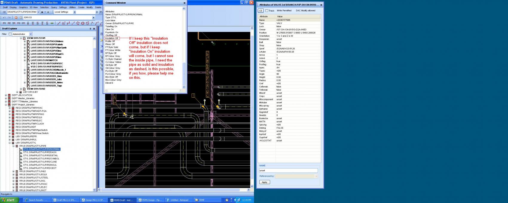
My immediate problem is that the insulation is showing on my pipe.
Above is the "STYL" been applied to the pipe (as the Criteria for the RRUL is "All Branch") as much as I know the "Insulation off" so why is the insulation been shown ? Could the Cats/Specs be set wrongly for the insulation ?
It might have to do with the dlevel 6. I am not sure about it but below is an extract from the draft user guide part 1.
The STYL attributes, with their defaults, are as follows:
Tube flag TUBEF OFF Centreline flag CLIN ON Piping Symbol flag PSYM ON Obstruction flag OBSTF OFF Insulation flag INSU OFF Profile flag PRFG OFF P-line flag PLFG ON Drawing Level DLEV 0 Frontface Pen FFPEN Pen 1 Centreline Pen CLPN Pen 4 Backface Pen BFPEN OFF Obscured Pen OBPN OFF P-line Pen PLNP 5 Member line Pen MLNP OFF
TUBEF, CLIN, PRFG, PLFG, PSYM, OBSTF and DLEV are standard PDMS display representation controls and are not described here. (See the PDMS DESIGN Reference Manual for details.)
If INSU is ON, Piping Component Insulation will be drawn using the frontface pen (FFPEN). The outline of the piping Components will be hidden by the insulation in hidden-line views. If insulation and Components are required to be displayed, two similar views (that use different Styles) will need to be defined and superimposed
Our project is a semisub and we have a GRID framework below the rig...
The GRID is made up of SCTN (pos 0 Up)...these are under a STRU/FRMW in the heirachy...
I want to do plans on the rig in various areas but show the GRID system...
However these GRID are been cancelled out by all the PANE and other model elemants above...
Is there something I can change on the STYL to make the GRID show through no matter what....
What is the Dlevel on STYL ? I've searched on the Draft User Guide but it's not showing anything...all the pen info is there (BFPEN, PLNP, MLNP etc)
another question for draft...
I want to show insul/tracing with special rule.. this would be ok..but I want to at the same time show - pipe without insul
as
- Tubeflag On Insulation Off + FFStyle SolidThick FFColour Yellow
and only for insulated parts want to show -
- Tubeflag On Insulation On + FFStyle Dotted FFColour Cyan ... of course this is a styf definition
I definend rrul that is ok...
But I am not abble to get full solid line INSIDE of INSUL and at the same time show Dotted line only for insulated parts.... it means, I will be very close to Design representaion, where we can set for displaying of Insulation
- insul transl ON translucency 25 ... ?
Specially it is usefull when insulation has small thickness,or has a special purpose... to show in draft (I finished my piping sketch programs, which makes completely all labels, dimesnions, welds,mat desc, slopes etc... including bolts(without running of bach isogen) + borders for ins/tracing) but.. much better would be to
show even INSUL on the piping elements.....(not only scalled bigger diameter and not with different colour - this I know)
I know 1 trick how to do it...but.... I must create a copy of view, one covers second,and in first will be shown only INSUL repr style, in second only for piping elements without insul...
is there any CHANCE ... or AVEVA still did not avake?
2 overlapping views with different representation rules is one option.
But in 12 you have something new that maybe can help you by adding automatically 2d symbols that represent insulation.
Try to have a look at C:\AVEVA\Plant\PDMS12.0.SP6\Manuals\Docs\PDMS User Bulletin12.0.pdf chapter 16.6 Symbolic representation of model objects.
I have never tried with insulation. But I think it could do a good job.
Other info: C:\AVEVA\Plant\PDMS12.0.SP6\Manuals\Docs\DRAFT Administrator Application User Guide.pdf chapter 7 2D Symbolic Representation Administration
And: C:\AVEVA\Plant\PDMS12.0.SP6\Manuals\Docs\Catalogues and Specifications User Guide.pdf chapter 4.1.16 Draft Symbol Sets
Thank you Corrado,
but it has some small problem.... I wrote program for general using for every company..so if I'd even test this method(I heard about it, but unfortunately in 12.sp4 was not possible to create hierarchy memb in paragon, in 12.sp6 yes...) - then every company must use this (in my opinion to complicated) philosophy....much better is to control via rules. well in this case I will keep just different colour (maybe line style) + borders of Ispec/Tspec shown automatically in draft.
Thank you for your effort.